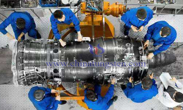
Molybdenum Silicate Coating for Niobium Tungsten Alloy Combustor of Engine
- Details
- Category: Tungsten Information
- Published on Thursday, 18 July 2019 22:45
Bipropellant attitude and orbit control engine is an important part of modern space vehicles and strategic and tactical weapons, which is widely used in orbit control and attitude adjustment. In recent years, with the development of new aircraft or weapons, the requirement for engine performance has been increasing. It requires that specific impulse be increased and chamber pressure be increased, so as to reduce propellant consumption and engine weight, prolong engine life or increase the range of strategic weapons.

The allowable temperature of the thrust chamber is one of the main factors determining the specific impulse of the engine, while the working temperature and anti-erosion performance of the thrust chamber are determined by the materials of the thrust chamber and the performance of the high-temperature anti-oxidation coating. At present, the Nb-Hf alloy coated with silicide is mainly used as combustion chamber in the dual-component liquid rocket engine for orbital guidance and attitude control of spacecraft in China. The coating process and system are slurry sintered Si-Cr-Ti coating and Si-Cr-Ti-Hf coating. Its working temperature is about 1400 ℃.
In order to further improve the service life of the engine nozzle with niobium tungsten alloy at high temperature, the researchers used a niobium tungsten alloy as the combustion chamber of the engine and prepared a composite molybdenum silicide coating system on the combustion chamber surface. The coating prepared by this method can raise the working temperature of the engine combustion chamber to 1660 degrees C and improve the engine performance. The high temperature margin extends the life of the engine through the following technical schemes:
(1.1)Preparing the first molybdenum target and the second molybdenum target, in which the first molybdenum target is used to prepare the molybdenum coating from the straight section of the niobium tungsten alloy combustor to the inner surface of the throat, and the second molybdenum target is used to prepare the molybdenum coating from the outlet section of the niobium tungsten alloy combustor to the inner surface of the throat.
(1.2) The first molybdenum target is mounted on the vacuum cathode arc deposition equipment on the inner surface. As the cathode, the arc spot moves up and down on the first molybdenum target surface by electromagnetic field control, the arc spot position on the first molybdenum target surface by controlling the current size, and the arc spot on the first molybdenum target surface by controlling the frequency of current change. Velocity of movement from surface to bottom;
(1.3) Place a niobium tungsten alloy combustor so that the straight-line section of the niobium tungsten alloy combustor is downward. The first molybdenum target is located in the inner part of the niobium tungsten combustor, so that the axis of the first molybdenum target coincides with the axis of the niobium tungsten alloy combustor, and the contact between the first molybdenum target and the niobium tungsten alloy combustor is avoided. The niobium tungsten alloy combustor acts as an anode.
(1.4) Deposition of Molybdenum Coating from the straight section of niobium tungsten alloy combustor to the inner surface of throat was completed by vacuum extraction and process control.
(1.5) The second molybdenum target is mounted on the vacuum cathode arc deposition equipment on the inner surface. As the cathode, the arc spot moves up and down on the second molybdenum target surface by electromagnetic field control, the arc spot position on the second molybdenum target surface by controlling the current size, and the arc spot on the second molybdenum target surface by controlling the frequency of the current change. Velocity of movement from top to bottom on the surface of timber;
(1.6) Place a niobium tungsten alloy combustor so that the exit section of the niobium tungsten alloy combustor is downward. The second molybdenum target is located in the inner part of the niobium tungsten alloy combustor, so that the axis of the second molybdenum target coincides with the axis of the niobium tungsten alloy combustor, and avoid the contact between the second molybdenum target and the niobium tungsten alloy combustor. The niobium tungsten alloy combustor acts as an anode.
(1.7) Deposition of Molybdenum Coating from the exit section of niobium tungsten alloy combustor to the inner surface of throat was completed by vacuum extraction and control of process conditions.
Step (2) Depositing Molybdenum Coating on the outer surface of niobium tungsten alloy combustion chamber;
Step (3) The niobium tungsten alloy combustor after depositing molybdenum coating is treated by vacuum activation and cladding, and the composite silicide coating system is prepared. The specific method is as follows:
(3.1) The infiltration material is loaded into the graphite crucible, and the niobium tungsten alloy combustion chamber is embedded in the graphite crucible with the infiltration material, so as to ensure that the whole combustion chamber is embedded in the infiltration material of the graphite crucible.
(3.2) The activator is loaded into the activator evaporator.
(3.3) The activator evaporator is loaded into the first vacuum furnace, the graphite crucible is loaded into the second vacuum furnace, and the activator evaporator and the graphite crucible are connected.
(3.4) Formation of molybdenum silicide coating by encapsulation activation reaction
Test surface: The working temperature of the engine can be increased to 1660 ℃, the specific impulse and high temperature margin of the engine can be significantly improved, and the engine life can be prolonged. After the vacuum thermal test, the engine life can reach more than 11 hours, the specific impulse can reach 319 s, and the high temperature margin can be increased by 100-150 ℃.
- Tungsten Alloy Manufacturer & Supplier, Chinatungsten Online: www.tungsten-alloy.com
- Tungsten News & Prices of China Tungsten Industry Association: www.ctia.com.cn
- Molybdenum News & Price: news.molybdenum.com.cn
- Tel.: 86 592 5129696; Fax: 86 592 5129797; Email: sales@chinatungsten.com


 sales@chinatungsten.com